
A modern command center requires more than just a large screen. The core is aggregating the right operational sources onto an easily readable surface: field cameras, building BMS, IoT dashboards, SCADA, maps, and operator workstations. This article focuses on the signal integration architecture for COB LED screens, without assuming a fixed number of ports, cameras, or card configurations.
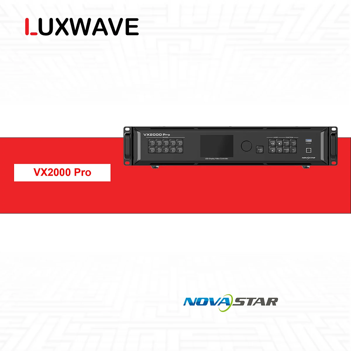
!NovaStar VX2000 Pro Multi-Source Processor
At Luxwave, the correct approach is to separate three layers: data sources, processing/splicer layer, and LED display layer. Luxwave is an authorized distributor of NovaStar, BOE, and PixelHue, allowing LED screens, processors, and integration coordination to be designed within a unified framework. The overall context of a monitoring room can be further explored in the article LED Screens for Command Centers and Monitoring Hubs.
Why Integrate BMS, CCTV, and IoT onto a Single Wall?
Command centers need a unified operational picture because incidents rarely occur within a single, isolated system. A temperature alert from the BMS might require cross-referencing with area cameras, IoT sensor status, and floor plans. If each system is confined to a small screen or separate computer, operators must piece together context under high-pressure situations.
LED walls enable the placement of critical sources in a stable layout: an overview map in the center, cameras by area, BMS/SCADA in status monitoring zones, KPI dashboards at the periphery, and priority areas for incidents. With fine-pitch COB LED screens, the benefit is amplified by a seamless surface without bezels interrupting maps, MEP diagrams, equipment labels, or charts. This is why command centers often require screens as an operational infrastructure, not merely display devices.
However, "putting it on a single wall" does not mean cramming all cameras and dashboards simultaneously. A well-designed system must prioritize information: which sources are always displayed, which are called up by shift, which appear only upon alerts, and which are used for meetings or reports. This informs the selection of the splicer, receiving cards, screen layout, and operational procedures.
What Layers Constitute the Integrated Signal Architecture?
The overall architecture can be described sequentially: IP camera sources, BMS, IoT/sensors, and operator PCs feed into the processing/splicer layer; the splicer aggregates sources and creates multi-window displays; processed signals go to receiving cards for display area mapping and redundancy organization; finally, the COB LED screen. This sequence sounds simple, but each layer requires technical schematic analysis rather than a list of discrete devices.
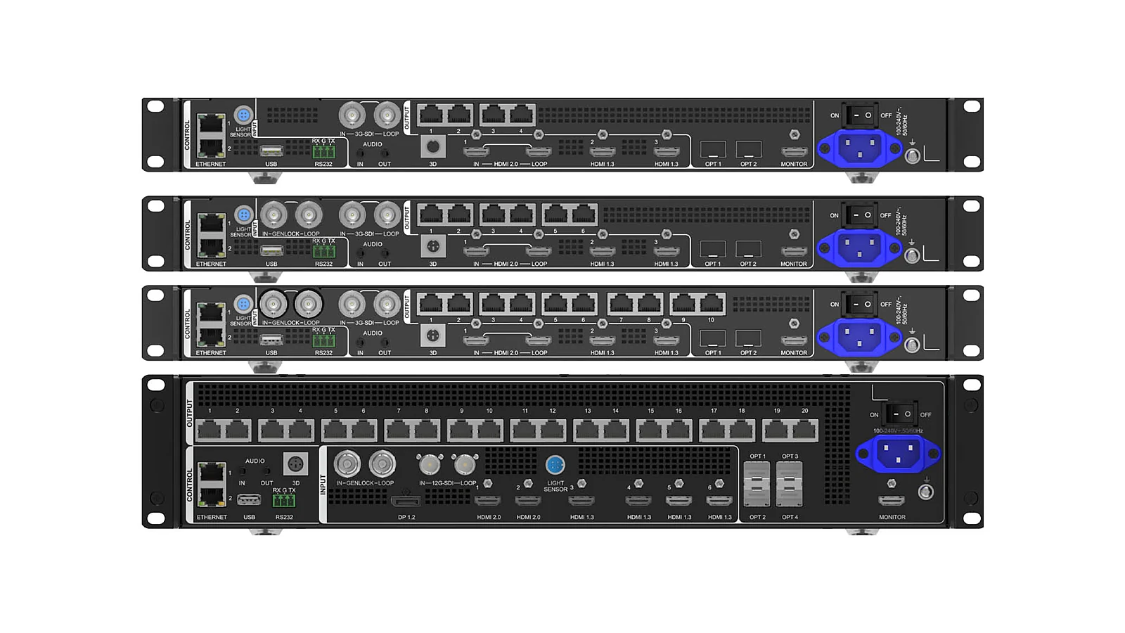
!Command Center Signal Processing Equipment (Splicer)
At the source layer, IP cameras typically involve ONVIF/RTSP, BMS often uses Modbus/BACnet, and IoT/sensors can communicate via MQTT or API. Operator PCs might output dashboards, SCADA, GIS, VMS, or web browsers. Not all sources connect directly to the processor: many data sources require intermediary software to convert them into dashboards, alerts, or preset commands.
In the processing layer, NovaStar H series, the NovaStar VX Pro family, or PixelHue Q8/P20 can receive video sources, create windows, generate layouts, recall presets, and manage redundancy. For large systems, modular splicers like the NovaStar H series or multi-screen systems like PixelHue Q8 need to be configured based on actual cards, sources, and outputs. Processor capabilities should not be inferred from model names without knowing the installed cards and intended layout.
At the LED layer, receiving cards map display areas to cabinets, manage signal transmission to the screen, and participate in N+1 redundancy plans when required. For command centers, N+1 designs must be included in the drawings: primary and backup paths, fault handover procedures, and whether operators can see fault status.

What is the Difference Between Display-Only and Event-Driven Alerts?
There are two significantly different levels of integration. Level one is display-only: streaming cameras, BMS dashboards, SCADA screens, maps, or IoT interfaces are presented on the wall in a predefined layout. This level is suitable when operators proactively monitor from native applications. It requires a stable processor, logical layout, and convenient presets, but the core business logic remains within each source system.
Level two is event-driven alerts: the system not only displays but also reacts to alarms. When the BMS signals an issue, a sensor exceeds a threshold, or VMS/CCTV detects motion, coordinating software can send commands to the splicer to change windows, zoom into relevant sources, change alert area colors, or recall a specific incident response preset. This layer significantly enhances command center functionality as operators don't need to manually search for information across multiple windows.
These two levels dictate different project scopes. Display-only can start with source matrices, resolution, window placement, and preset recall methods. Event-driven requires additional data mapping: which alarms are critical, which system generates them, which cameras are relevant, which statuses need acknowledgment, and whether the layout reverts automatically after an alarm is cleared.

Which Integration Protocols Need Prior Survey?
IP cameras typically require ONVIF and RTSP surveys. ONVIF helps discover, manage, or standardize partial interoperability between IP video devices; RTSP is commonly used for video streams. In practice, many projects still route through a VMS/NVR rather than connecting each camera directly to the splicer. The most suitable method depends on the existing camera system, access rights, security policies, and the number of concurrent streams required.
!Multi-Source Connection Ports
BMS integration often requires surveying Modbus, BACnet, or the building management system's proprietary API. BMS data is not always visual; it includes measurement points, statuses, alarms, or dashboard pages. For display-only scenarios, the BMS/SCADA interface can be presented from an operator PC. For event-driven systems, the integration software must be able to read alarms, understand area codes, and trigger the correct layout on the splicer.
IoT/sensors are generally more flexible but can also be more complex. MQTT is suitable for the publish/subscribe model for sensor data, while APIs are typically used for querying or controlling specific endpoints. Topics, payloads, update frequencies, authentication, network access, and alert rules must be clarified before promising any automated behavior on the LED wall.
The key point is that the LED wall does not inherently become a BMS, VMS, or IoT platform. The LED wall is the display layer; the processor/splicer is the image layout layer; the integration software is the data interpretation and event coordination layer. Clearly defining the roles of these three layers facilitates project acceptance and minimizes unmet expectations.
How to Select a Processor/Splicer for a Command Center?
Processor selection must begin with the workflow, not the port count listed in brochures. Key questions to answer include: which sources feed the system, which are video, which are dashboards, the resolution of each source, the number of concurrent display windows, presets to be recalled, MVR/preview requirements, redundancy needs, and who has permission to change layouts during a shift. With this schematic, selecting NovaStar H series, VX Pro, or PixelHue becomes well-founded.
NovaStar H series is suitable for modular splicer applications, aggregating multiple sources and creating multi-window displays based on card configurations. The VX Pro family is appropriate for integrated processor/controller needs in simpler operational setups. PixelHue Q8/P20 excels in environments with numerous sources, multiple screens, backup requirements, and advanced workflows. The article What's the Difference Between Switchers and Splicers? provides foundational knowledge if project teams confuse live source switching with multi-window layout composition.
There is no single correct model for every command center. A building monitoring room with a few dashboards and critical cameras differs from a SOC/NOC with numerous sources, presets, and alert layers. Fixed maximum camera counts should also be avoided, as capacity depends on card configuration, stream resolution, decoder/VMS, concurrent layouts, and redundancy methods. The professional approach is to create a source matrix and then finalize equipment based on the design drawings.
What to Consider for 24/7 Operation?
Command center systems typically run continuously, so the design must extend beyond successful initial setup. The COB LED layer requires consideration for heat dissipation, power supply, color stability, and maintenance capabilities during shifts. Implementation data from China highlights concepts like adaptive thermal compensation, AI calibration, and edge-blending to maintain stable images during extended operation; specific features must be confirmed based on the chosen screen, processor, and software.
The first common pitfall is failing to distinguish between data sources and visual sources. An RTSP stream is a visual source; a BACnet alarm or MQTT message is event data. To make alarms change the screen layout, software is needed to interpret this data and control the splicer or preset system. If only dashboard visuals are sent to the screen, the system remains at a display-only level, despite user expectations for automated alerts.
The second pitfall is the lack of operator scenarios. Command centers are not operated based on pretty diagrams; they run on shifts. It's crucial to define what shifts typically view, what to do during incidents, who can change presets, which alerts auto-zoom, which alerts only flash, and how to prioritize multiple concurrent alerts. These decisions directly impact the layout and coordinating software.
The third pitfall is neglecting network security. CCTV, BMS, and IoT systems often reside on different VLANs, security domains, or access policies. Displaying them on a wall should not equate to broadly expanding access privileges. Projects must coordinate with IT/OT teams to define network traffic, service accounts, API keys, firewalls, logs, and operator permissions.
The fourth pitfall is treating redundancy as an accessory. For command centers, N+1 redundancy must be designed for critical points: power supplies, signal paths, receiving cards, processors, or control lines, depending on criticality. If screen clusters are distributed across multiple areas, fiber optic transmission might be included in the design for flexible deployment distances. The Command Center Solutions page outlines the operational context of IOCs/NOCs/SOCs, where even a minute of display loss can impact incident response procedures.
Conclusion: What is the Recommended Configuration Process?
The correct process should start with system surveys, not equipment names. The first step is to create a source inventory: cameras/VMS, BMS, SCADA, IoT, GIS, operator PCs, meeting sources, and backup sources. The second step is to specify the protocol or output method: ONVIF/RTSP, Modbus/BACnet, MQTT, API, HDMI, SDI, IP video, or browser. The third step is to map layouts, presets, concurrent windows, and alert rules.
Only then should splicers, controllers, receiving cards, and COB LED screens be selected. If the project is display-only, the focus is on layout quality, signal stability, and rapid operation. If the project is event-driven, additional coordinating software, alarm mapping, device APIs, and scenario testing are required. For both levels, products like NovaStar VX2000 Pro, NovaStar H series, or PixelHue Q8/P20 must be integrated into the actual schematic rather than chosen based on intuition.
Luxwave can manage the COB LED screens, NovaStar/PixelHue processors, display signal schematics, and coordinate with the project's software integration team. The BMS, VMS, SCADA, or IoT software aspects will still require the original system provider to supply protocols, access rights, and business rules. When all parties agree from the architectural design phase, the LED wall will not just "display images" but become an intuitive operational interface for the entire system.
Pitfalls
Common mistakes
- Grouping all needs into a "display cameras on the wall" request without differentiating between cameras, BMS, IoT, SCADA, operator PCs, and alert streams.
- Selecting a splicer before surveying protocols; a BMS system might use Modbus or BACnet, cameras ONVIF/RTSP, and IoT might use MQTT or proprietary APIs.
- Designing for display-only while expecting the system to auto-zoom on alerts; event coordination requires intermediary software and clear operational presets.
- Committing to specific port counts, camera numbers, or window counts without understanding processing cards, source resolutions, concurrent layouts, and redundancy requirements.
FAQ
Frequently asked questions
What protocols are used for integrating BMS and CCTV onto LED screens?
CCTV typically uses ONVIF for device management and RTSP for video streams. BMS commonly uses Modbus or BACnet for exchanging status, alarms, and measurement points. LED screens do not directly read all these protocols; a software layer or gateway is needed to aggregate data and then send visuals, dashboards, or events to the processor/splicer.
What is the difference between display-only and event-driven alerts?
Display-only means presenting cameras, dashboards, SCADA, or BMS pages on the wall as fixed visual sources. Event-driven is a higher level: when the BMS signals a fire, overheating, or CCTV detects motion, the system automatically changes display areas, highlights relevant sources, or recalls an alert preset.
What type of processor or splicer does a command center need?
The appropriate processor depends on the number of sources, resolution, concurrent windows, layout, and redundancy requirements. NovaStar H series, VX Pro family, or PixelHue Q8/P20 can all handle source aggregation and multi-window composition, but card configurations must be finalized after surveying actual sources.
Who handles the BMS/CCTV/IoT integration software?
Luxwave is responsible for the LED screens, processors, display signal flow, and technical coordination with the software integration team. The connection for BMS, VMS, SCADA, or IoT typically requires the software/BMS/VMS provider to supply APIs, protocols, access rights, alert rules, and operational testing.
Can a camera automatically zoom in when an alert occurs?
Yes, if the system is designed for event-driven alerts. When software receives an alarm from BMS, IoT, or VMS, it can trigger presets on the splicer to zoom into a camera, change the layout, or highlight the alert area. Specific capabilities depend on device APIs, coordinating software, and the alarm acknowledgment workflow.
Should the number of cameras on an LED screen be committed to upfront?
It is not advisable to commit to a fixed camera count without surveying the system. Display capacity depends on stream resolution, concurrent windows, layout, processing cards, bandwidth, decoder/VMS, and redundancy requirements. The correct approach is to create a source matrix and operational scenarios before finalizing the configuration.
References
- 1.ManufacturerGenuine NovaStar
- 2.ManufacturerGenuine PixelHue
- 3.ResearchChinese Control Room Integration Compilation